KBR Horse Net &
Least Resistance Training Concepts (LRTC)

Volunteers Training for Emergencies

  KBR / LRTC Survival School
PREVENTING TRAILER ACCIDENTS

February 18, 2014

  PART THREE:
LIGHTS AND VISIBILITY

Please note: This feature is a continuation from Part One.

In Part One we discussed proper hitches, how to determine if a hitch is designed for the load you intend, and if your trailer properly coupled to your tow vehicle. In Part Two we discussed running gear "from the ground up." In Part Three we will discuss electrical systems and visibility.

  Electricity and Lighting

Electrical Systems

From our observations, electrical system issues are the number one source of nuisance problems with trailers. On trailer inspection days, easily over half the trailers checked have some kind of an electrical problem ranging from lamps that don't work to completely inoperable brake systems.

Dust incursion into lamp holders and switches, poor grounds and wiring insulation that is worn through from vibrating against metal components are the most common causes of these problems.

To make sense of trailer wiring, how to prevent problems and how to fix electrical failures, let's review the trailer's electrical system starting at the tow vehicle.

A power cord from the trailer connects to a receptacle on the tow vehicle. For most trailers this connection will involve a 6 or 7 pin plug and receptacle. There are standardized wiring configurations for these plugs and receptacles. It is important that all plugs and receptacles be wired according to these standards in order for trailer lights and brakes to work properly and to prevent damage to the tow vehicle's or trailer's electrical system due to crossed wiring.

Illustrated below are diagrams for proper plug and receptacle wiring.

Please note!

  • Not all harnesses conform to the standardized color codes although the purpose for each pin connection illustrated is correct. If in doubt use a test light to verify which color wire is being used for each purpose.

  • Many late model pickups wire the center contact of the 7-way system to the vehicle's backup lights.
When replacing aged and troublesome plugs and cables, we typically purchase pre-molded plug and cable sets rather than continually chase electrical problems.

When replacing aged cables, we will install a heavy duty terminal strip on which to make our connections. The terminal strip is reliable and it makes future circuit diagnosis and wiring changes much easier.

An inexpensive and reliable way to reroute chafed or worn wiring, or to protect exposed wiring, is to use copper tubing or conduit. Tubing or conduit can be run inside or underneath the trailer. Be sure to seal the ends with silicone to keep out debris and to prevent stinging insects from building nests inside.

Also make sure that you have a very good ground connections for the ground lead of your electrical cable. DO NOT rely on the trailer ball to complete the ground circuit. The ball will conduct electricity but the circuit's resistance will change, which can confuse electronic brake controllers!

A typical interior conduit run.

All states and provinces have some kind of minimum lighting standards for trailers. Generally, in addition to standard tail / brake / signal lamps, trailers are required to have amber clearance lamps at or near the forward corners visible to the front and sides, and red clearance lamps at or near the rear corners, visible to the rear and sides. Trailers over 80 inches in width are required to have a three-lamp DOT "Identification Lamp" cluster.

A particular headache out west where it can get very dusty results from dust intrusion into various lamps. We have found that over the long term sealed lamps and LED fixtures eliminate intermittent dust caused failures.

In many states, longer trailers are required to have an additional amber clearance lamp approximately mid-point along each side of the trailer. We routinely install such a lamp regardless of trailer length and place it at the widest point of the trailer. At night a lamp that indicates the widest part of the trailer helps drivers better judge the position of their trailers and helps prevent striking posts and other objects in the dark.

  Reflectors and Striping

Amber reflectors are required on each side near the front and red reflectors are required on each side near the rear as well as on the rear if combination tail lamp-reflectors aren't used.

Reflectors are relatively inexpensive however the adhesive type do tend to fall off during rough service or when exposed to extreme elements. We have found the stick-on types that also have mounting holes to be very reliable. We'll stick them into place, then secure them with 1/8 inch pop rivets. A small amount of extra installation effort can save on labor later on.

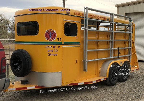
Many states require DOT red and silver striping on larger trailers. We find them to be a great safety feature for all trailers, especially trailers that are painted darker colors. Aside from increased visibility, if we have a lighting failure or we are parked on the side of the road, a thorough striping job can prevent a costly accident.

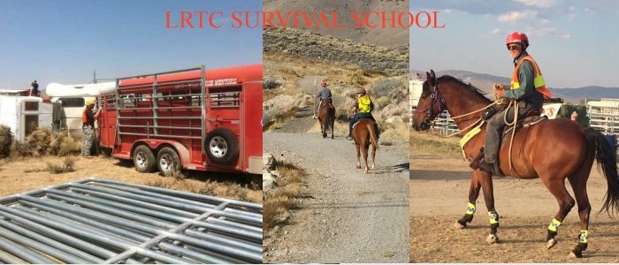
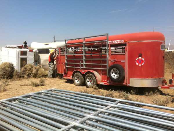
This is the standard lighting and striping configuration for the rescue team's trailers.
(We also add a distinctive reflective color stripe that matches the color code of equipment carried.)

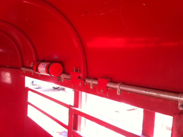
In addition to required lighting, we typically install an automatic backup lamp, utility loading lamps and interior lamps. The interior lamps should be designed to provide adequate light for loading and working inside the trailer but not produce outside glare when transporting animals in a lighted trailer. Trailers also have automatic backup alarms that can be manually temporarily disabled when backing up near agitated animals.

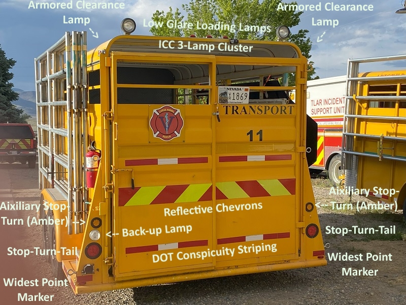
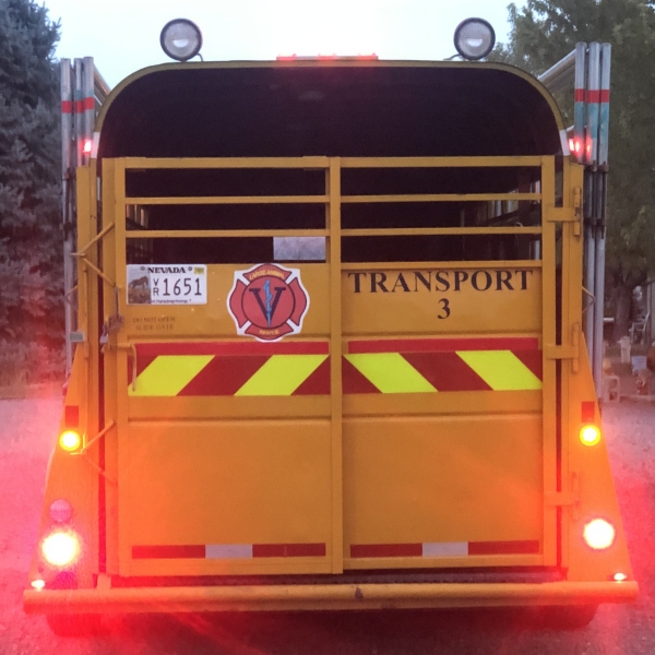
Amber auxiliary stop and turn lamps above the standard red lamps placed closer to "line of sight"
can attract additional attention from following motorists when reducing speeds or changing direction.

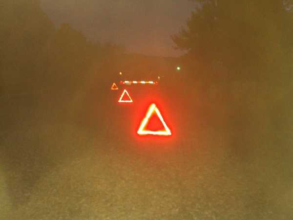
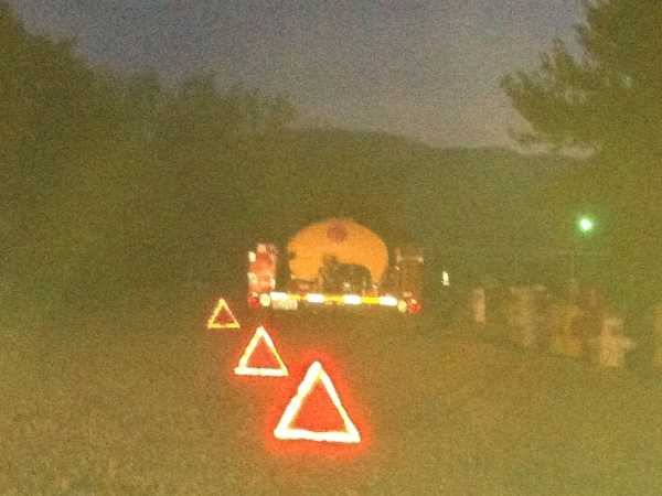
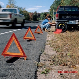
Most states also require any vehicle (including trailers) that are over 80 inches wide to carry reflector stands or triangles that can be put out to warn approaching motorists if the vehicle is disabled on or alongside the roadway.

Placement.

2-way traffic: One reflector within 10 feet of the vehicle, a second reflector approx. 100 feet behind the vehicle and a third reflector approx. 100 feet in front of the vehicle.,

1-way traffic: Same as above except that the third reflector shall be placed approx. 200 feet behind the vehicle.
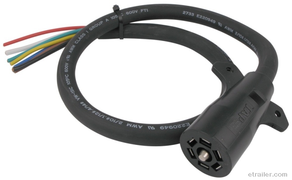
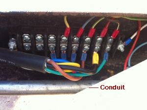
           

Continue to Part Four

Return to Part Two


Press Back to return to the page which brought you here

Return to Technical Large Animal Rescue and Evac Page

Return to LRTC Wild Horse Mentors

Return to KBR Training Page